AI Coding Tools for 3D Printing: A Complete Guide to Creating Objects with Words
swiftwand swiftwand.ai
In particular, a 1kg spool of filament costs ¥2,500 (approximately $17). An 8-hour print warped and failed. That’s ¥300 (~$2) in material costs plus ¥26 (~$0.17) in electricity — and 8 irreplaceable hours lost. Repeat this three times, and the mental and financial damage becomes impossible to ignore.
In the previous article on “Multi-Material AI 3D Print Optimization,” we explored the design paradigm of combining different materials. The more complex a multi-material part, the higher the cost of print failure. This article explains how digital twin 3D print AI simulation detects and eliminates “failures” in virtual space before physical printing.
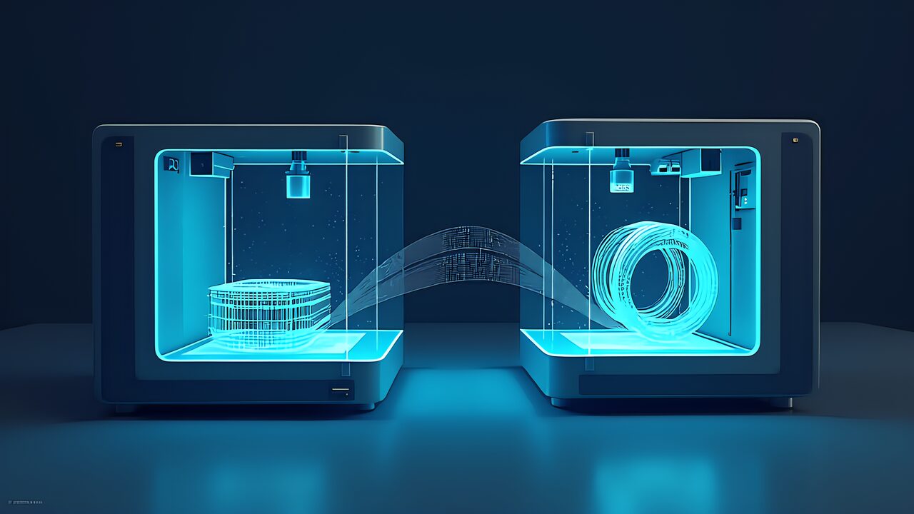
In conclusion, to understand digital twin 3D print AI simulation, we need to precisely define “digital twin” in the 3D printing context.
Furthermore, the digital twin concept widely used in industry refers to a “digital replica of a physical product, process, or system.” It digitally reproduces the behavior of physical-world entities in real-time — aircraft engines, factory production lines, urban infrastructure.
Additionally, in 3D printing, a digital twin consists of three layers:
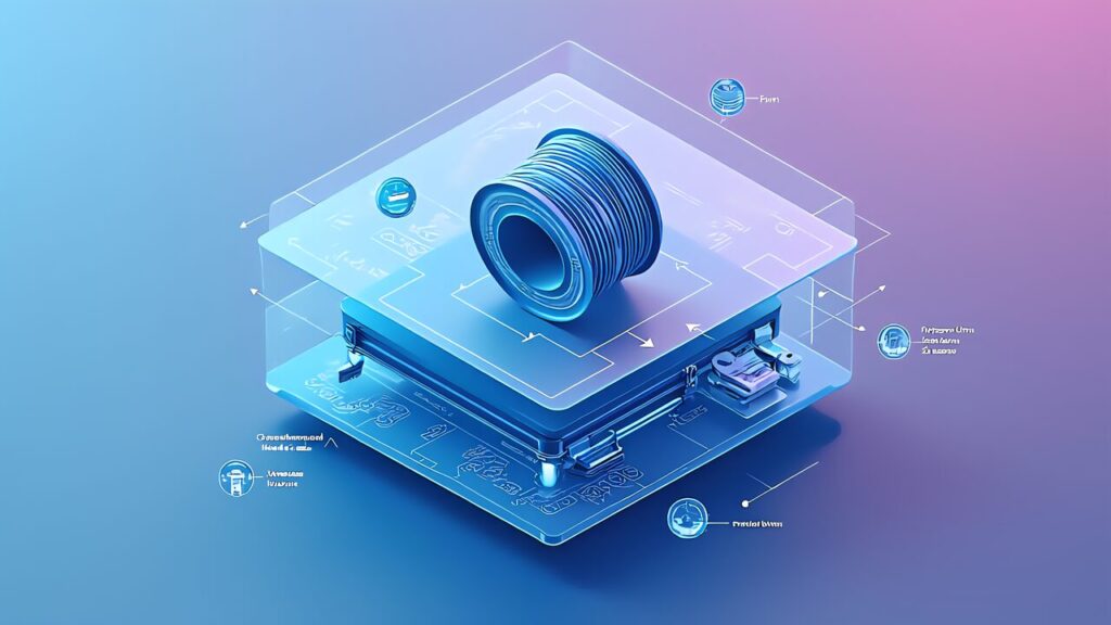
Layer 1: Printer Digital Twin. This models the printer’s mechanical characteristics — nozzle diameter, maximum speed, acceleration, bed temperature distribution, and more. The same G-code produces different outputs on different printers due to individual variations. The digital twin reproduces these individual differences digitally.
Key Point
Layer 2: Material Digital Twin. This models filament physical properties — melting point, thermal expansion coefficient, elastic modulus, viscosity, and more. Even within the same PLA designation, properties vary subtly between manufacturers and production lots.
Layer 3: Print Process Digital Twin. This combines the printer and material digital twins to simulate the entire printing process. It predicts cooling rates, residual stress, and deformation at each layer.
The Siemens × NVIDIA solution covered in “Digital Twin 3D Print” implements all three layers at industrial scale. This article focuses on simulation methods accessible to individual makers.
Specifically, digital twin 3D print AI simulation has become essential for three reasons.
Reason 1: Material costs keep rising. Engineering filaments like PC and Nylon cost ¥5,000-¥8,000 (~$33-$53) per kg. A single failed large-format print can waste ¥1,000+ (~$7+) in material alone.
Reason 2: Print times are getting longer. As makers tackle more ambitious projects — larger parts, finer resolution, multi-material combinations — print times of 12-24 hours are common. Failed prints waste not just material but irreplaceable time.
Reason 3: Multi-material complexity multiplies failure modes. As explored in the previous article, combining materials with different shrinkage rates, melting points, and thermal properties introduces failure modes that don’t exist in single-material printing.
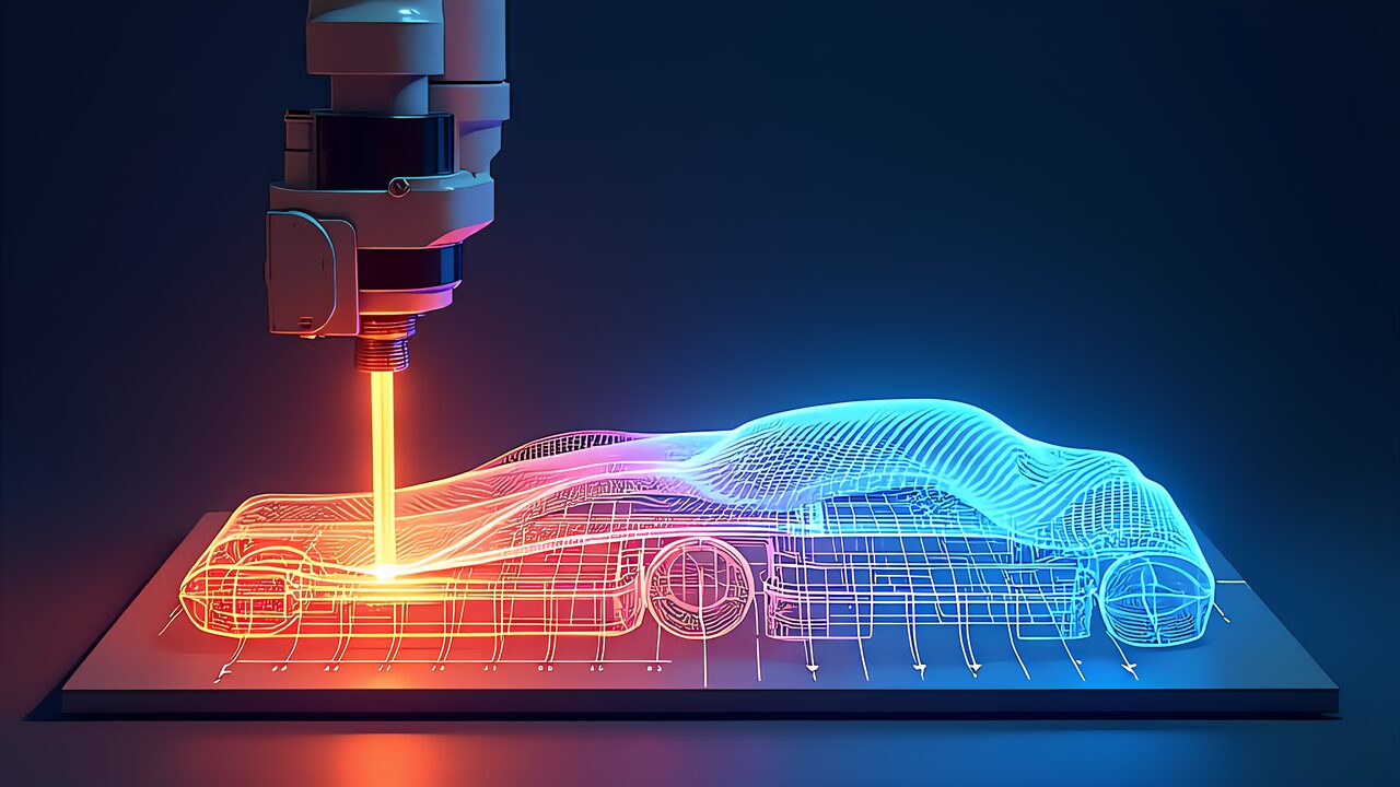
Moreover, the simplest form of digital twin is G-code visualization — previewing exactly what the printer will do before it does it.
OrcaSlicer’s built-in preview provides layer-by-layer visualization with color-coded speed, flow rate, and temperature. This catches obvious issues like missing supports, insufficient infill, and problematic overhangs. Time investment: 2-3 minutes per model.
What to look for: Unsupported overhangs exceeding 45°, bridging distances over 10mm without support, thin walls below 0.8mm (2 perimeters), and rapid travel moves across open areas that cause stringing.
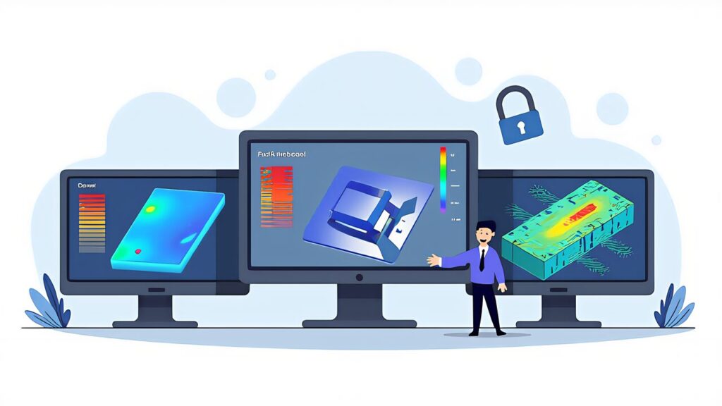
Additionally, FEA (Finite Element Analysis) predicts how a printed part will behave under load — before printing a single layer.
Fusion 360 Simulation (included in the ¥92,400/year subscription, approximately $620/year) provides cloud-based FEA that handles linear static analysis, modal analysis, and thermal analysis. In testing, for a bracket designed with infill rate of 40% and wall thickness of 2.0mm, the simulation predicted a safety factor of 5.0, while actual destructive testing showed breakage at 115% of the predicted load — conservative but accurate predictions.
The specific workflow is as follows: Material property setup — select PLA, PETG, PC, etc. from Fusion’s material library. For custom materials, input at minimum tensile strength, Young’s modulus, and Poisson’s ratio. Constraint definition — set surfaces where the part will be fixed (bolt holes, bonding surfaces) as “fixed constraints.” Load condition setup — set loads in Newtons to reproduce actual usage conditions. Include self-weight by calculating material density × volume × gravitational acceleration. Mesh generation and solver execution — default mesh size of 0.5-1.0mm is generally sufficient with analysis times of 1-5 minutes. Result interpretation — confirm that maximum von Mises stress is below 1/3 of the material’s yield stress (safety factor of 3.0 or higher).
Furthermore, as a free alternative, FreeCAD’s FEM Workbench (with built-in CalculiX solver) is available. The UI is less polished, but it handles basic linear static analysis adequately. The setup procedure is nearly identical to Fusion 360.
Key Point
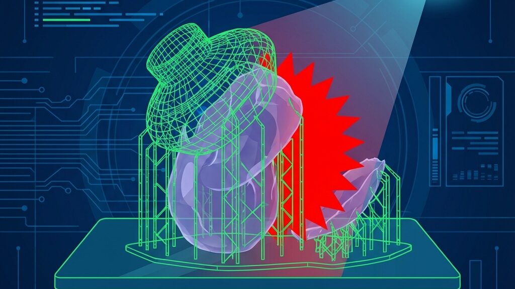
Also, warping in FDM prints is caused by residual stress during the post-print cooling process. Full thermal simulation falls within the domain of industrial tools, but the following simplified rules can prevent most problems:
Don’t let large flat surfaces contact the bed: For bottom surfaces exceeding 100mm × 100mm, set brim width to 5mm or more. For parts exceeding 150mm × 150mm, 10mm+ brim is recommended.
Avoid abrupt wall thickness changes: Residual stress concentrates at boundaries between thick and thin sections. Where wall thickness jumps from 1mm to 4mm, create a gradual transition in 1mm increments.
Add fillets to corners: Right-angle corners become stress concentration and warping initiation points. Adding fillets with a radius of 2mm or more distributes residual stress.
Use an enclosure: The Bambu Lab P1S (from ¥69,000, approximately $460) enclosure maintains uniform temperature during printing, reducing warping from uneven cooling rates. Internal temperature maintains room temperature +15-25°C, reducing warping occurrence by over 70% especially for ABS and PC prints.
| Material | Shrinkage Rate | Warping Risk | Enclosure Required | Recommended Bed Temp |
|---|---|---|---|---|
| PLA | 0.3-0.5% | Low | No | 60°C |
| PETG | 0.5-0.8% | Low-Medium | Optional | 80°C |
| TPU | 0.5-1.0% | Low | No | 50°C |
| ABS | 0.7-1.1% | High | Yes | 100°C |
| Nylon | 1.5-2.0% | Very High | Yes | 80°C |
| PC | 0.6-0.8% | High | Yes | 110°C |
In other words, digital twin 3D print AI simulation is evolving from rule-based prediction to AI-driven prediction.
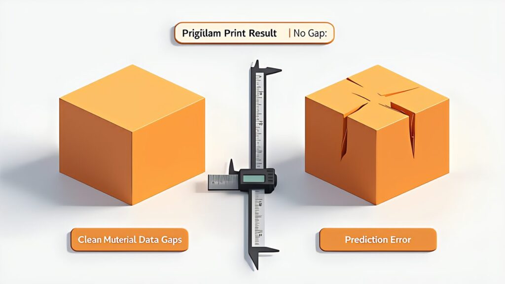
Vision-based pre-print analysis: AI models trained on thousands of failed prints can analyze a 3D model’s geometry and predict failure probability before slicing. CMU’s research demonstrates 85%+ accuracy in predicting print failures from model geometry alone.
Real-time simulation acceleration: NVIDIA’s Modulus framework uses physics-informed neural networks (PINNs) to accelerate thermal simulation by 1,000x compared to traditional FEA. What took hours now takes seconds, making real-time simulation practical for desktop makers.
Closed-loop digital twin: The ultimate goal is a system where the digital twin updates itself based on real print data. Each print feeds data back to refine the simulation model, making predictions increasingly accurate over time.
In conclusion, digital twin 3D print AI simulation transforms the workflow from “design → print → fail → redesign → reprint” to “design → simulate → print once successfully.” The technology exists today at every budget level — from free G-code visualization to cloud-based FEA.
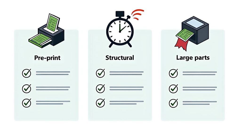
Furthermore, start with G-code preview in OrcaSlicer (free, 2 minutes per model). Add FEA analysis for structural parts (Fusion 360 or FreeCAD). Apply the thermal deformation rules for every print. These three layers of simulation will dramatically reduce your failure rate.
In the next article, “AI 3D Print Tech 2026 Roundup,” we’ll synthesize all seven articles in this series into a comprehensive technology maturity map and investment guide for the year ahead.
For more information, visit Siemens Digital Twin.