Metal Filament 3D Printing Complete Guide: How to Make Real Metal Parts at Home with Sintering in 2026
swiftwand swiftwand.ai
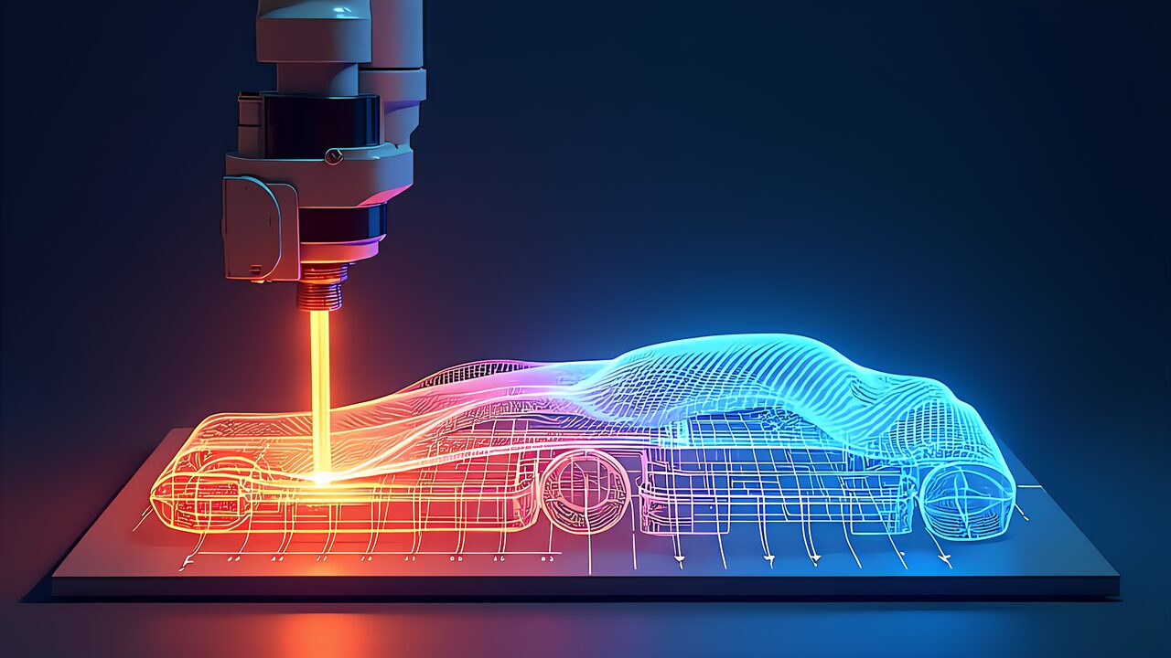
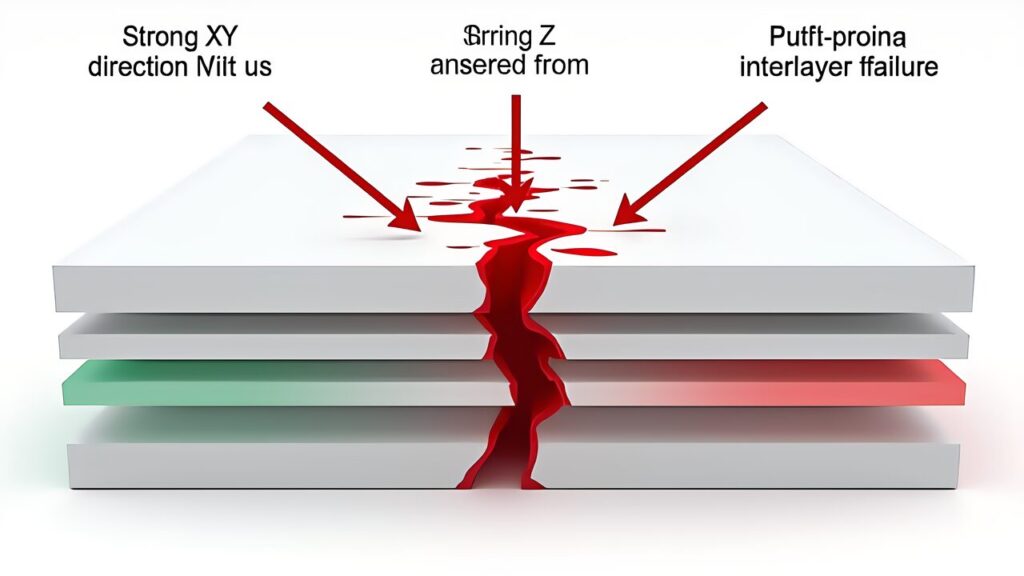
Standard FDM 3D-printed parts typically achieve tensile strengths of only 50–65 MPa, far below aluminum 6061-T6’s 310 MPa. The root cause lies in the layer-by-layer fabrication process itself. Molten filament deposited in successive layers creates weak inter-layer bonds where adhesion depends solely on thermal diffusion between the current and previously deposited layer. This fundamental limitation means Z-axis strength drops 30–50% compared to in-plane properties.
The anisotropic weakness makes FDM parts unsuitable as structural components. However, embedding continuous carbon fiber into the print transforms this equation entirely. Continuous fiber reinforced parts achieve 400–800 MPa in the fiber direction, rivaling machined aluminum and even approaching aerospace-grade composites. The critical challenge becomes fiber placement optimization: determining where, in which direction, and how much fiber to embed.
Inter-layer adhesion in FDM depends on three interconnected factors. First, the temperature differential between the newly deposited layer and the existing surface determines molecular diffusion depth. Second, the contact time during which both layers remain above the glass transition temperature affects bond formation. Third, applied pressure from the nozzle influences void content at the interface. Even under optimal conditions, the resulting bond strength reaches only 60–80% of the bulk material strength, creating a persistent weak point in any vertically loaded structure.
PLA demonstrates this clearly with nominal tensile strength of 50–65 MPa in-plane but Z-axis values dropping to as low as 25–35 MPa. Engineering materials like nylon and PETG show similar proportional reductions. This anisotropy means that a part designed for multi-directional loading will always fail at its weakest layer interface, regardless of how strong the in-plane properties might be.
Markforged pioneered commercial continuous fiber 3D printing with its proprietary Continuous Filament Fabrication (CFF) technology. The Mark Two and X7 printers use a dual-nozzle system: one for the matrix material (Onyx, a chopped carbon fiber–filled nylon) and another for continuous fiber reinforcement (carbon, glass, Kevlar, or HSHT fiberglass). According to Markforged’s Technical Data Sheet (ASTM D638), Onyx achieves 37 MPa at break and 40 MPa at yield. Meanwhile, continuous carbon fiber (CCF) reinforced parts reach up to 800 MPa tensile strength per ASTM D3039.
However, independent testing reveals important nuances. Research from the University of Galway (Vedrtnam et al., published in Composites Part C, 2023) measured continuous CF Markforged specimens at 418±9.86 MPa. This gap between TDS maximum values (800 MPa in the fiber direction) and real-world results (400–600 MPa) is significant. The discrepancy arises from fiber volume fraction variations, void content, and testing methodology differences. For practical engineering calculations, using the 400–600 MPa range provides a more conservative and reliable design basis.
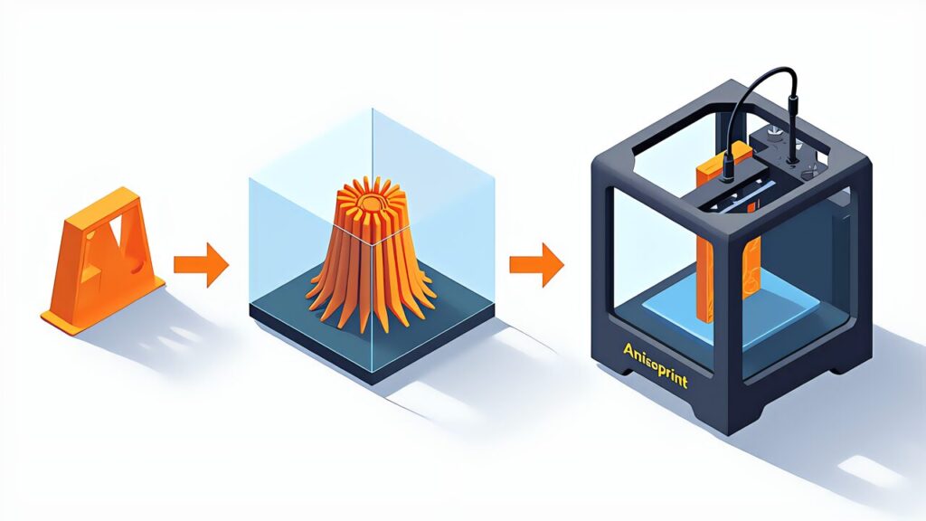
In contrast to Markforged’s closed ecosystem, Anisoprint differentiates through an open material strategy. The Composer A4 (build volume 297×210×140 mm) supports nozzle temperatures up to 270°C and achieves fiber volume fractions up to 60%. Beyond carbon fiber, Anisoprint supports basalt fiber (CBF), which offers better thermal resistance and lower cost for applications where maximum strength isn’t the primary requirement.
The tensile modulus for CCF reaches 60 GPa, approaching aluminum alloy territory (69 GPa for 6061-T6). This means continuous fiber 3D-printed parts can match aluminum’s stiffness while being significantly lighter. The specific strength (strength-to-weight ratio) of continuous CF composites is 2–4 times that of aluminum, making them ideal for weight-critical applications in aerospace, automotive, and robotics.
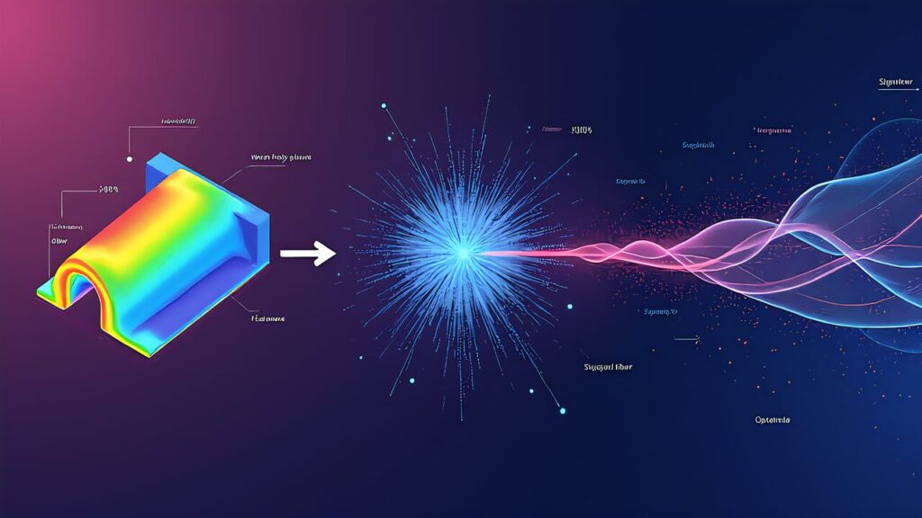
Research in AI-driven fiber path planning has accelerated rapidly since 2023. The fundamental approach uses finite element analysis (FEA) to compute the stress field across a part, then automatically routes continuous fibers along principal stress directions. This stress-based placement ensures maximum structural contribution from every fiber segment, eliminating the “dead fiber” problem common in manual placement.
The ACM SCF ’23 paper “More Stiffness with Less Fiber” demonstrated that optimized fiber placement achieves higher stiffness with fewer fibers than conventional approaches. By aligning fibers precisely with principal stress trajectories, the researchers showed that fiber utilization efficiency increases dramatically, reducing material cost while improving performance.
A May 2025 arXiv paper (2505.03779), later published in ACM Transactions on Graphics, introduced simultaneous optimization of topology, layer count, and fiber orientation. This multi-objective approach improved failure load by up to 33.1% compared to baseline designs. The algorithm simultaneously determines where material should exist (topology), how many layers to use, and the optimal fiber angle at each point.
MIT’s MechStyle AI system (January 2026) generates topology-optimized geometries that can be directly manufactured via additive processes. Additionally, Additive Flow’s Formflow software provides commercial FEA-to-fiber-placement pipelines that integrate with Anisoprint’s Aura slicer, making optimized fiber placement accessible to production environments.
Even theoretically optimal fiber paths must respect physical manufacturing constraints. The most critical is minimum bend radius. Continuous carbon fiber buckles and fractures when bent too sharply. For typical CF/PC combinations, the minimum bend radius is approximately 9.8 mm, varying between 5–10 mm depending on fiber bundle thickness and resin type. AI path planning algorithms must incorporate this as a hard constraint, mathematically expressed as fiber path curvature κ ≤ 1/r_min. Ignoring this constraint produces paths that either break fibers during printing or cause nozzle jams.
Translating theory into practice requires a systematic workflow. The following five-step process uses the Anisoprint Composer A4 and Aura slicer to implement FEA-driven continuous fiber path design.
After designing the part in CAD, run a static structural analysis in your FEA software of choice. Suitable tools include FreeCAD with CalculiX (open source), Fusion 360 Simulation (Autodesk, supports nonlinear analysis), and Additive Flow Formflow (cloud-based topology optimization with direct Aura integration). The FEA output should include principal stress direction maps as vector fields, von Mises stress contour plots to identify critical regions, and displacement analysis to verify boundary conditions.
Convert FEA stress results into 2D mask images for each print layer. High-stress regions (above a threshold, typically 30–50% of maximum von Mises stress) are marked as fiber placement zones. This can be automated with Python scripts processing FEA output files, or performed manually using the mask-based control in Aura slicer. The mask approach lets engineers precisely specify fiber placement areas while the slicer handles detailed path routing within those regions.
Load the 3D model into Aura slicer and configure the following parameters for optimal fiber placement results.
| Parameter | Recommended Value | Notes |
|---|---|---|
Before printing, verify fiber paths in Aura’s preview mode. Confirm that fibers cover high-stress regions identified in the FEA analysis. Pay particular attention to areas around holes, cross-section changes, and load introduction points where fiber reinforcement is most critical. After printing, perform destructive or non-destructive testing to validate mechanical properties against design requirements.
Compare test results with FEA predictions. If measured strength falls short of targets, increase fiber volume fraction in critical areas, adjust fiber orientation angles, or refine the stress threshold for mask generation. This iterative optimization loop typically converges within 2–3 cycles for most structural parts, with each iteration providing valuable empirical data to improve simulation accuracy.
| Material | Tensile Strength (MPa) | Elastic Modulus (GPa) | Test Standard | Source |
|---|---|---|---|---|
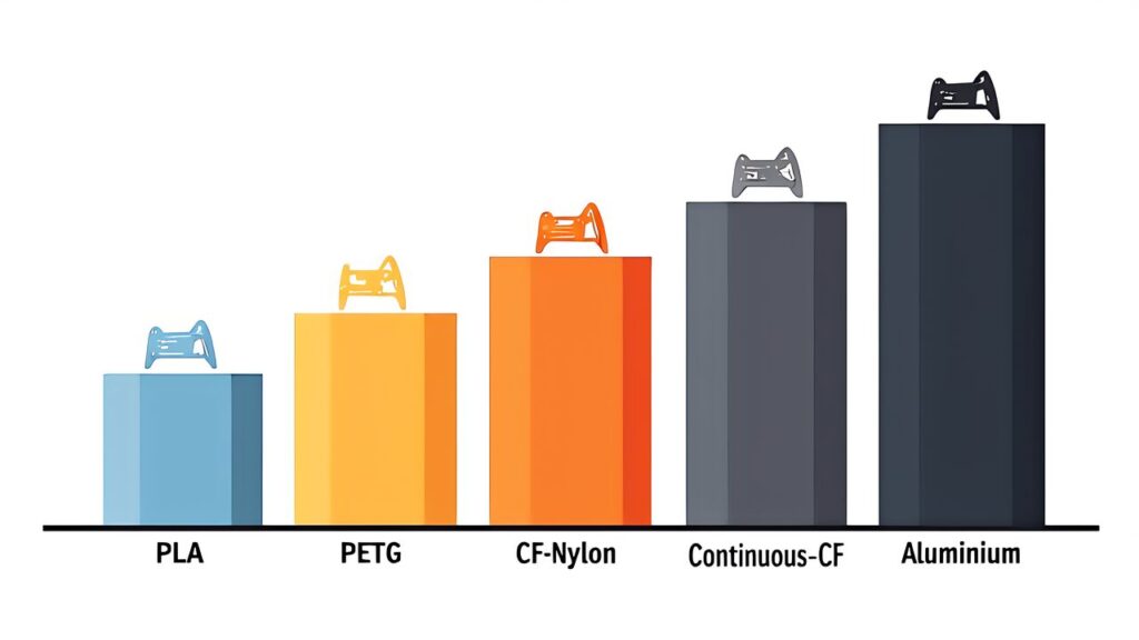
The data reveals a striking progression. Standard PLA at 50–65 MPa represents the baseline FDM capability. Adding chopped carbon fiber to nylon roughly doubles strength to 71–140 MPa. The quantum leap occurs with continuous fiber reinforcement, which achieves 418–800 MPa depending on fiber volume fraction and test conditions. This places continuous CF 3D prints in the same performance envelope as machined aluminum (310 MPa), but with the design freedom of additive manufacturing.
From a specific strength perspective (strength divided by density), continuous CF composites outperform aluminum by a factor of 2–4×. This weight advantage is transformative for applications in UAVs, racing components, prosthetics, and any scenario where every gram matters. The combination of AI-optimized fiber placement and continuous fiber 3D printing creates a pathway to mass-customized structural parts that were previously only achievable through traditional composite layup processes.
The ISO/ASTM 52967:2024 standard now provides a formal framework for characterizing fiber-reinforced additive manufactured parts. This standardization is essential for industry adoption, as it establishes consistent testing methodologies and acceptance criteria that enable engineering confidence in printed structural components.
The future trajectory of continuous fiber 3D printing with AI path planning is clear. 3D printers are evolving from prototyping devices into structural part manufacturing systems. Platforms like Markforged provide the vertically integrated hardware foundation for industrial adoption. Meanwhile, Anisoprint’s open material strategy expands material selection flexibility. On the software side, AI and ML optimization algorithms continue to push the boundaries of what manual design can achieve.
For more information, visit Markforged: Continuous Fiber 3D Printing.
Challenges remain, particularly around minimum bend radius constraints, inter-layer shear strength reliability, and the need for broader standardized testing. However, as FEA-to-fiber-path pipelines mature through tools like Additive Flow Formflow and direct Aura integration, the gap between simulation prediction and manufacturing reality continues to narrow. For engineers and designers ready to move beyond prototyping, continuous fiber 3D printing with AI path planning represents the most accessible route to high-performance composite structures.