Metal Filament 3D Printing Complete Guide: How to Make Real Metal Parts at Home with Sintering in 2026
swiftwand swiftwand.ai

In other words, “lightweight, strong, and beautiful.” When designing parts for 3D printing, these three requirements are always in conflict. Thicker walls increase strength but add weight and material cost. Decorations improve aesthetics but create stress concentration points that weaken structure. Even experienced engineers rely on intuition and trial-and-error to balance these three factors.
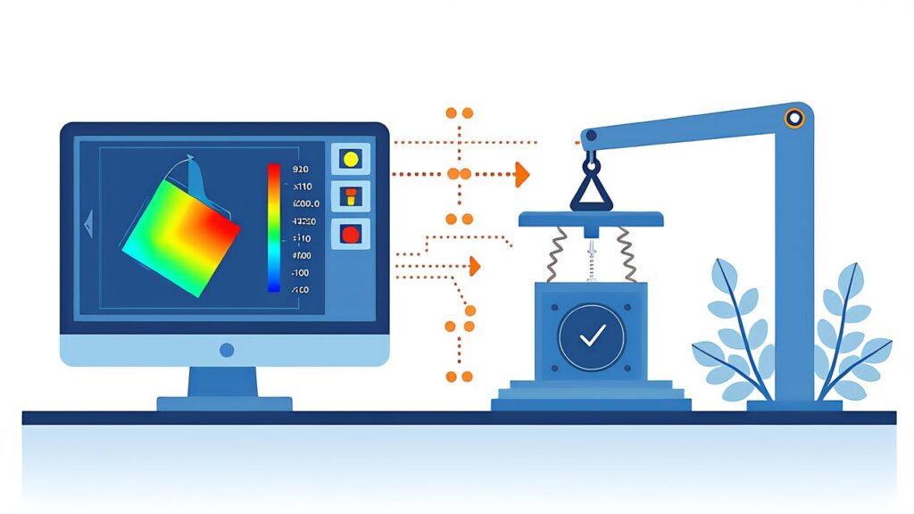
In our previous article on AI 3D print real-time correction, we explained auto-correction during the printing process. This article shifts perspective to “before printing.” As a practical guide to AI generative design for 3D printing, we demonstrate specific workflows for automated design technology integrated with FEA (Finite Element Analysis).
Specifically, before discussing AI generative design for 3D printing, let’s clearly distinguish two commonly confused concepts.
Topology optimization starts from a single human-designed CAD model and removes material based on load conditions and constraints, returning one optimized shape. It’s “subtractive design,” yielding only one result.
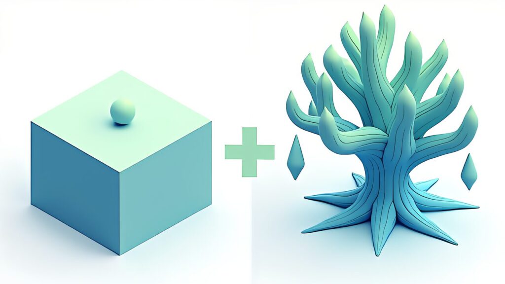
Generative design starts from retention zones, preservation zones, loads, and constraints, with AI generating multiple topologically distinct concepts. No human-designed shape is input. AI creates forms through “addition.” Results yield dozens to hundreds of variations for engineers to select from.
This difference is decisive for 3D printing. Topology optimization often optimizes within injection molding or CNC constraints, failing to leverage 3D printing’s unique fabrication freedom. Generative design actively explores “shapes only 3D printing can create” — organic lattice structures, streamlined wall thickness following stress paths, optimal hollow structure placement.

Additionally, the biggest breakthrough in AI generative design for 3D printing is MechStyle, developed by MIT CSAIL.
For example, when conventional generative AI stylized 3D models, only 26% remained structurally sound. AI prioritized appearance, thinning walls and creating stress concentration points. MechStyle solved this by integrating FEA simulation feedback into the generative AI stylization process.
MechStyle’s core is a feedback loop alternating Score Distillation Sampling (SDS) and FEA:
FEA computation is expensive, so MechStyle uses adaptive scheduling — running FEA frequently in early iterations when shape changes are large, and less frequently later when changes are minor. This reduces total FEA calls by approximately 60% without quality loss.
Key Point: MechStyle achieves 100% structural integrity while maintaining visual style freedom. The key insight: constrain vertices in high-stress regions while allowing free deformation elsewhere.
Design a shelf bracket supporting 50N (approximately 5kg) load with safety factor 5.0, using PETG filament on an FDM printer with 0.4mm nozzle.
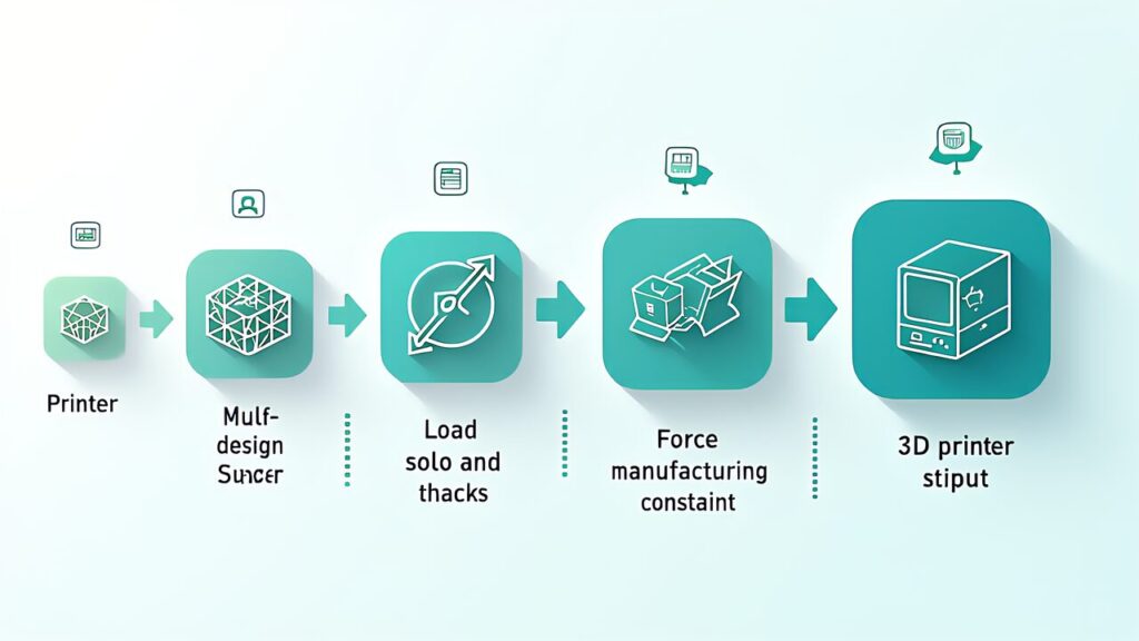
Define retention geometry (bolt holes, mounting surfaces), obstacle geometry (clearance for other parts), and design space (where AI freely explores).
The selected candidate (Candidate C) was exported as STL and sliced in OrcaSlicer. Print conditions: PETG, nozzle 240°C, bed 80°C, 0.20mm layer height, 25% gyroid infill. Print time approximately 2 hours 15 minutes, material usage approximately 12g.
Destructive testing (average of 3 specimens) showed failure load of 287N — 15% above the FEA-predicted safety factor of 5.0 (50N × 5.0 = 250N). FEA predictions had conservative error, confirming the safety factor setting was appropriate.
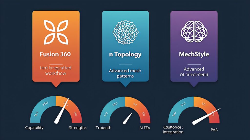
Additionally, the most accessible tool for AI generative design for 3D printing is Autodesk Fusion 360’s generative design feature.
Select “Additive” manufacturing method and specify build direction (for overhang control), minimum wall thickness (0.8mm+ for 0.4mm FDM nozzle), and minimum overhang angle (45° for supportless printing).
Fusion’s solver generates 10-50+ design variations. Compare mass (60% weight reduction cases reported), maximum stress (verify below yield stress), and printability (overhang analysis, support requirements).
The critical limitation of current generative design tools: they assume isotropic material properties. FDM prints are inherently anisotropic — strength varies dramatically with print direction.
| Material | XY Tensile Strength | Z Tensile Strength | Z/XY Ratio | Optimal Nozzle Temp |
|---|---|---|---|---|
| PLA | 55MPa | 35MPa | 64% | 215°C |
| PETG | 50MPa | 22MPa | 44% | 245°C |
| ABS | 40MPa | 28MPa | 70% | 250°C |
| PolyMax PC | 68MPa | 41MPa | 60% | 270°C |
Notably, PETG shows the most pronounced Z-direction strength loss (44%), making print orientation selection even more critical than for PLA or ABS. ABS can improve Z/XY ratio to 85% with acetone vapor post-processing.
| Print Direction | Failure Load (avg of 3) | FEA Ratio | Support Volume |
|---|---|---|---|
| Direction A (wall face as bottom) | 287N | 115% | 2g |
| Direction B (shelf face as bottom) | 198N | 79% | 8g |
| Direction C (side as bottom) | 94N | 38% | 15g |
A 3.05x difference between Direction A and C. Direction C aligned primary load with delamination direction, failing at just 38% of FEA prediction. This data demonstrates that print orientation selection is equally important as the generative design itself.
Key Point: Generative design produces optimal shapes, but FDM anisotropy means those shapes can be 3x weaker in the wrong orientation. Always validate print direction against primary stress vectors.
For more information, visit nTopology Official.