Generative Design Guide 2026: Let Fusion Propose the Shape
swiftwand swiftwand.ai
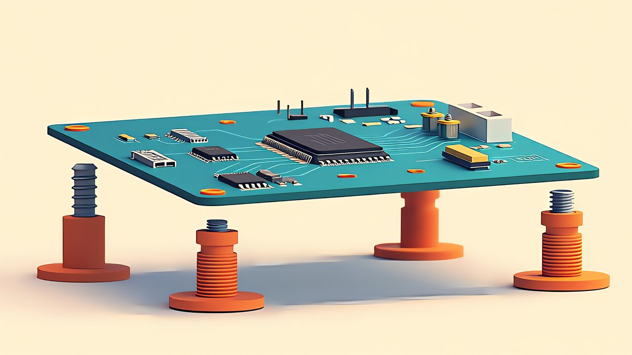
The box is designed, the openings line up — but the board is still swimming freely inside. PCB mounting is where an enclosure stops being a container and starts being a product. Leave a board loose and three things happen: the openings drift out of alignment (a board that moves 1 mm moves every port 1 mm), vibration works the solder joints, and every cable tug transfers straight to the components. This article covers the four practical mounting methods, how to size them, and what goes wrong when you pick the wrong one.
| Method | Extra parts | Re-opening tolerance | Design effort | Best for |
|---|---|---|---|---|
| Screws into bosses | Screws only | Low | Small | Boxes assembled once and left closed |
| Heat-set inserts | Inserts + screws | High | Medium | Boxes opened and reassembled repeatedly |
| Snap / retaining clips | None | Medium | Large | Production-leaning designs with no visible screws |
| Card-edge slots | None | High | Small | Boards that can simply slide into place |
Screws driven directly into printed bosses are the simplest option: a self-tapping screw bites into a plastic cylinder and the job is done. The catch is longevity — by the third disassembly the threads strip and you are reprinting the base. Heat-set inserts cost roughly a minute of pressing work per board but give you metal threads that survive indefinitely; if you build one unit, the difference is noise, but across many units or many disassemblies it dominates. Snap fits eliminate hardware entirely at the cost of careful flexure design. And the often-overlooked fourth option, the card slot, needs no fasteners at all.
For the Raspberry Pi 5, the official mechanical drawing (RP-008347-DS-1) gives you everything: 85 × 56 mm board, mounting holes on a 58 × 49 mm pitch, 2.7 mm hole diameter, 3.5 mm offset from the edges. The Arduino UNO R4 WiFi documents its mounting holes and board outline in its official datasheet (ABX00087). For custom boards, your CAD already knows: KiCad can export the board as STEP, letting you do interference checks directly in mechanical CAD. Board thickness deserves respect too — JLCPCB lists standard FR-4 thicknesses of 0.4 / 0.6 / 0.8 / 1.0 / 1.2 / 1.6 / 2.0 mm with a finished-thickness tolerance of ±10%, so a nominal 1.6 mm board can arrive anywhere between 1.44 and 1.76 mm. If you hold a board in a slot, size the groove for the range, not the nominal.
A boss is not just a cylinder — four dimensions need decisions. Height: the underside of a PCB is never flat; through-hole legs and pin headers protrude a casual 3 mm. Measure the tallest protrusion and add about 1 mm. Diameter: Protolabs Network’s design guideline calls for at least one hole-diameter of material around any screw hole. For an M3 clearance hole (3.25 mm), that means roughly 3 mm of wall around it — a boss outer diameter in the 9 mm range. Seat: the top of the boss should be flat so the board sits on a defined surface rather than digging in under torque. Fillet: the junction between a cylinder and a flat base is the textbook stress concentration, and it is exactly where bosses crack. A 0.5–1 mm radius at the root visibly changes survival rates.
The hole sizes follow the standard FDM rules: clearance holes at screw diameter +0.25 mm, self-tapping holes at screw diameter −0.25 mm. And define every boss center as a variable in one place, referenced by both the base and the lid — write the same coordinate twice by hand and it will eventually disagree with itself.
Boards with small M2.5 mounting holes and crowded undersides — the Raspberry Pi 5 being the canonical example — suit metal standoffs, which give clean fixed heights and metal threads at both ends. Boards with M3 or larger holes and a few millimeters of required clearance work fine on printed bosses with heat-set inserts. Keep M2.5 and M3 insert stock on hand and you can mount most hobby boards on demand.
When a board’s connectors sit on one or two edges, a pair of grooves in the enclosure walls can hold it with no fasteners at all. Print orientation matters, and the groove must accommodate the board-thickness tolerance noted above — a slot sized for exactly 1.6 mm will reject a 1.7 mm board. Add a light lead-in chamfer and the board slides in by feel. For boxes that open frequently, the combination of a card slot plus a lidded case is hard to beat for assembly time.
Tighten all four corners hard on a slightly uneven set of bosses and the middle of the board bows. Three escapes exist: don’t rigidly fix all four points (locate on one or two, let the rest simply support); make one hole the datum and slot the others slightly so stress has somewhere to go; and put torque into words — “quarter turn past contact” written in an assembly note beats “snug” remembered differently every time. A one-page assembly memo is the smallest version of a habit that pays off across every project.
The four methods are bosses, heat-set inserts, snaps, and slots; choose by how often the box will be opened. Bosses need four decisions — height (measured protrusion +1 mm), outer diameter (one hole-diameter of wall), a flat seat, and a root fillet. Clearance holes at +0.25 mm, self-tap at −0.25 mm, board thickness treated as 1.6 mm ±10%. Locate on one point, relieve the others, and write the torque down.