Automate Plant Watering with Home Assistant: From Notifications to Pump Control
swiftwand swiftwand.ai
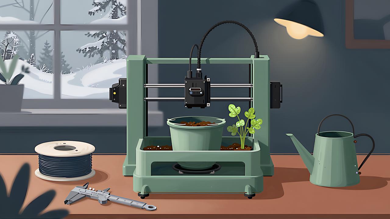
When pots come indoors for winter, it gets hard to judge how often to water. Leave home for a few days on a trip and the mix may be bone dry when you return. Self-watering pots are sold ready made, but their shapes and sizes do not always fit the shelf or windowsill you have in mind. Try to 3D print your own and you hit a different set of walls: the outer pot leaks, the inner pot does not fit, and you are not sure whether PLA is acceptable.
This article contains affiliate links. As an Amazon Associate, we earn from qualifying purchases.
This article checks how bottom watering works against university Extension publications, pins down the wall conditions for leak-free prints from Prusa test results, and chooses a material from data sheets. It then reports our own test in which Claude Sonnet 5 wrote CAD code for a self-watering pot at different effort (thinking) settings. The headline: at low effort the model returned working code in one minute, but when the two parts were assembled, the bottom of the inner pot poked 82 mm through the bottom of the outer pot, even though every part matched the specified dimensions on its own.
Note that we did not print this design or run any leak or watering tests. What we measured was running the AI-written code, checking the geometry, and print time and material from a slicer.
A self-watering container differs from an ordinary pot in where the water exits. According to University of Maryland Extension, instead of a drain hole in the bottom there is an overflow hole in the side, and the growing mix sits on a perforated platform directly above the reservoir. Roots grow through the mix toward the water, and in most designs water is drawn up from the reservoir into the mix.
The mechanism is capillary action. The University of Kentucky publication AEN-157 on wicking containers explains that with bottom watering the plant receives water from below, held in the pores between soil particles by surface tension. The finer the particles, the more strongly they lift water against gravity. In that publication’s design, with the water level at the drain hole, capillary action moves water about 4 inches (about 10 cm) above it. The figure depends on the mix, so treat it as a guide for those conditions rather than a general value.
Overflow height controls overwatering. AEN-157 notes that the maximum water level is set by the position of the drain hole. However much you pour into the reservoir, the level cannot rise above the overflow. In a self-watering pot design, the overflow height is the upper limit to which the mix sits in water.
The same sources list advantages and drawbacks.
How many days you can skip watering depends on the plant, mix and room temperature. The sources say only “a few days,” and so does this article.
Translating the mechanism into design terms leaves three dimensions to decide.
The first is the maximum water level, that is, the overflow height. AEN-157’s example is a large tub about 16 inches wide and deep, with an overflow hole about 4 inches above the inside bottom, 5/16 to 3/8 inch in diameter, holding about 3.4 gallons. Those numbers do not scale to a tabletop pot, but the ideas do: make the overflow large enough for excess water to drain freely, and let its height set the reservoir volume.
The second is the wicking path. The mix can reach the reservoir through a fabric or string wick, or through a column of mix that projects from the inner pot bottom into the water. Our test used the latter: a 40 mm diameter, 45 mm deep well projecting down from the center of the inner pot, with six 3 mm slits in the side so the mix touches water.
The third is the fill port. So you can add water without lifting the inner pot, attach a tube to the side of the outer pot. AEN-157 points out that an open fill port may attract mosquitoes and suggests a removable cap. Even for a small indoor pot, it is worth designing the cap in from the start. For a threaded cap, see our guide to 3D printed threads and inserts.
Also set the clearance between inner and outer pots as a dimension. Too tight and you cannot lift the inner pot to check roots; too loose and it tilts. Our tolerance and fit guide covers how to pick those numbers.
Measuring your shelf space, the pots you already own and test prints is much easier with a digital caliper, and it makes clearance numbers something you can verify rather than guess.
The inner pot may drain, but the outer pot holds water. FDM prints are built layer by layer, and under the wrong settings water seeps through gaps between layers.
The Prusa Knowledge Base puts the baseline for watertightness at no fewer than 3–4 perimeters per wall. Depending on geometry you can go to 5–6, but that is rarely necessary. If you cannot add perimeters, it also suggests widening extrusion by 5–10% over the default (0.4 mm to 0.44 mm).
More detail comes from Prusa’s watertightness test. Using a simple test cylinder, Prusa found the minimum number of perimeters for a watertight print in each material. The tests used specific filaments, and other brands may differ. The same article recommends printing at 0.15 mm layers with a 0.4 mm nozzle.
| Material | Minimum perimeters |
|---|---|
| ABS, ASA, CPE, PC, PP | 2 |
| TPEE | 3 |
| PETG, PLA, PA | 4 |
| HIPS, PVB | 5 |
The article reports that with thin walls (2–4 perimeters, 0.9–1.8 mm) material differences were clear: PP sealed best, while PETG, PLA and others leaked noticeably more. With thick walls (6 perimeters, 2–3 mm or more) there was hardly any difference between materials.
Its findings on where leaks come from also shape the design. The main leak sources were not the interfaces between layers but the seams formed when moving to the next layer and the boundary between solid infill and perimeters. The number of bottom solid layers matters less than perimeters, but it recommends at least five to be safe.
In vase mode (called Spiral vase in PrusaSlicer; the name varies by slicer), even a single perimeter was watertight in every tested material. There is no layer-change seam, which supports the conclusion that seams are the main culprit. Vase mode prints the bottom solid layers and then a single outer wall as a continuous spiral, so it cannot make a fill tube or internal dividers. It becomes an option if the outer pot is just a cylinder and bottom and the fill port is a separate part.
You can also seal after printing. Prusa mentions epoxy resin and smoothing the surface with acetone, while acknowledging the effort involved. It notes that acetone-smoothed ASA or ABS may not need extra perimeters, but acetone is a solvent that needs ventilation and this article does not cover the procedure. Two-part brush-on coatings (such as Smooth-On XTC-3D) exist; we mention one only as an example.
More perimeters also mean a stronger part. The relationship between perimeters and strength is covered in our guide to designing for strength.
PETG is often recommended for planters. But the reasons commonly given, “PETG absorbs less water than PLA” or “PETG leaks less,” are not consistently supported by published data.
On watertightness, Prusa’s test above found the same minimum of four perimeters for PETG and PLA, and both leaked heavily with thin walls. PETG has no watertightness advantage over PLA. In the comments on that article, Prusa also said the PETG tested had been left open in the office for weeks and that dried filament was not tested.
On absorption, manufacturer data sheets (TDS) disagree.
| Source | Conditions | PLA | PETG | ASA |
|---|---|---|---|---|
| Prusament TDS (moisture absorption, 7 days) | 24 °C, 22% humidity | 0.19% | 0.10% | 0.17% |
| Bambu Lab TDS (saturated water absorption) | 25 °C, 55% RH | 0.43% | 0.45% | — |
| Polymaker PETG TDS (max water absorption) | 23 °C, 70% RH, 12-day test | — | 0.51% | — |
In Prusament data PETG absorbs about half as much as PLA, but for Bambu Lab PLA Basic and PETG Basic the values are nearly identical. And these describe filament exposed to air, not immersed in water. The argument that PETG suits planters because it absorbs little water does not stand on this data.
So what is the case for PETG? Heat and UV. The Prusa PLA article says PLA softens and deforms above 60 °C and degrades in UV. Heat deflection temperatures (0.45 MPa) in the Prusament TDS are 55 °C for PLA, 68 °C for PETG and 93 °C for ASA. The Prusa PETG article describes PETG as resistant to water and moisture and suitable for most outdoor uses below 80 °C.
For a pot on a summer windowsill or in the sun, the chance that PLA deforms in heat and degrades under UV is the real reason to pick PETG. At what temperature it deforms depends on the location, so this article does not give a figure.
For full sun outdoors, ASA is also a candidate. The Prusa ASA article says ASA resists UV better than ABS, warps less and suits outdoor use, while also noting it needs ventilation when printing and tends to warp during the print. For a first material on a home printer, PETG is easier.
You will sometimes read that “PLA dissolves in water.” That is not correct. The Prusa article introduces the idea that PLA does not dissolve but may swell under some conditions and open paths for water, then reports that no leaks appeared in long-term tests of a Prusament PLA planter.
For an outer pot on a windowsill or anywhere it gets sun, PETG is the first candidate on heat and UV grounds.

 ポチップ
ポチップFor a pot growing herbs or salad greens, food safety comes up. We avoid firm claims here and pass on the manufacturer’s position as stated.
Prusa acknowledges that PETG is widely used in the food industry and often considered food safe, but it does not recommend printing anything that contacts food directly, such as tableware, with any filament including PETG. The main reason is the fine grooves between layers on the surface. The Prusa article on food-safe FDM printing names those grooves as a breeding ground for bacteria and notes that brass nozzles are not considered food safe. The watertightness article also states plainly that watertight does not mean food safe.
A planter is not tableware. Still, when growing edible plants, remember that the print is not guaranteed to be a food-contact material. Japan has a positive list system for food utensils, containers and packaging, enforced from June 1, 2020 with transitional measures ending May 31, 2025 (Consumer Affairs Agency). A homemade pot will not necessarily comply. This is a general overview, not legal advice; for how rules in your country apply to your pot and materials, ask the relevant authority or an expert. Prusa recommends coating with a certified food-grade epoxy for food use.
Now our own test. A self-watering pot is close to a simple solid of revolution, but the heights of the inner and outer pots, the rim, the wicking well and the fill port all have to agree. We wanted to see what happens when an AI writes it in one go. Illustrations from here on depict the situation; they are not photos of a tested part.
| Item | Details |
|---|---|
| AI | Claude Code CLI 2.1.283 with claude -p, model claude-sonnet-5, no tools, MCP or project settings |
| Conditions compared | Effort (–effort) at default, medium and low |
| Output | Python code using manifold3d 3.3.2 that writes STL files for the inner and outer pots |
| Checks | Closed solid, bounding dimensions, share of downward faces steeper than 45°, overlap, lowest point and side clearance when the two parts are assembled, slicing with the Bambu Studio CLI |
| Physical parts | Not printed; no leak or watering tests |
The request was a single specification in Japanese. The inner pot: 120 mm outer diameter at the top, 110 mm tall, 2.4 mm walls, a 40 mm diameter, 45 mm deep wicking well projecting from the bottom with six 3 mm slits and six 5 mm drain holes, and a 6 mm wide rim that rests on the top of the outer pot. The outer pot: at least 1.0 mm clearance per side, at least 50 mm reservoir depth and one fill port with a 16 mm inner diameter. Material PETG, 0.4 mm nozzle, 0.2 mm layers, both parts printable as oriented without supports (downward overhangs within 45°), and the outer pot must not leak.
We chose Python over OpenSCAD because we wanted to measure the overlap of the two parts numerically with Boolean operations. OpenSCAD can do the same. OpenSCAD is free software under GPL v2 for Windows, macOS and Linux. The latest stable release is 2021.01, and the official site suggests enabling the Manifold geometry engine in a development snapshot (downloads). Writing OpenSCAD with an LLM is covered in our guide to code CAD with LLMs.
Limitations first: each condition ran once. Rerunning the same condition could give different results. What follows records what happened in that one run, not general performance at each effort level.
Cost is the total_cost_usd value returned by the CLI.
| Condition | Time | Output tokens | Cost | Code | Assembly | Downward faces over 45° (inner / outer) |
|---|---|---|---|---|---|---|
| Default | 48 min 43 s | 256,000 (limit error) | $2.63 | No output | — | — |
| Medium | 48 min 05 s | 253,425 | $2.61 | 281 lines, ran first time | Valid | 0.05% / 0.03% |
| Low | 1 min 03 s | 6,445 | $0.08 | 269 lines, ran first time | Invalid | 9.88% / 2.83% |
| Low plus one fix | 5 min 45 s | 31,215 | $0.36 | 265 lines, ran | Invalid (elsewhere) | 0.04% / 1.49% |
We had a loop ready to feed errors back and ask for fixes, but every run that returned code ran without errors the first time.
At low effort the model returned code in 1 minute 3 seconds. Both pots were closed solids and sliced fine, and the dimensions matched the spec. Assembled, though, they did not work.
The cause was how the outer pot height was set. The code sized it only as reservoir depth plus headroom above the water, giving a total height of 73 mm. The inner pot measures 110 mm to the underside of the rim, and the well projects another 45 mm. With the rim resting on the outer pot, the lowest point of the inner pot sits 82 mm below the bottom of the outer pot. No per-part check catches this.
Separately, the inner pot floor projected horizontally from the well, so downward faces steeper than 45° made up 9.88% of the inner pot surface. As oriented, it could not be printed without supports.
When we passed those two findings back with numbers and asked for one fix, a revised version arrived in 5 minutes 45 seconds. The outer pot grew to 170 mm and the inner floor became a funnel, cutting overhangs to 0.04%. Both reported issues were resolved.
But the fill port had a different defect. Its tube ran from outside the outer pot past the center and overlapped the inner pot’s well. The bore also went straight through the opposite wall, leaving a 16 mm hole in the outer pot below the waterline. The code cut the bore with a cylinder longer than the outer pot diameter. The same construction existed in the first version, but it was hidden behind the larger defect of the inner pot piercing the outer bottom, so our first round of checks missed it. Asking for fixes gets the requested spots fixed, and defects you did not mention stay. After any fix, rerun every check from the start and review the checks themselves.
Medium effort took 48 minutes 5 seconds and $2.61 but returned a design that holds up when assembled. It made the underside of the rim a 45° slope so it prints without supports, calculated where that rim meets the inner corner of the outer pot, and derived the outer pot height from there. Overlap was zero, the gap between the well tip and the outer bottom was 8.0 mm and side clearance about 1.2 mm. Downward faces over 45° were 0.05% on the inner and 0.03% on the outer pot.
As specified, the code opened with its dimension variables. An excerpt (comments translated):
MAX_OVERHANG_DEG = 45.0  # max overhang considered support-free (angle from vertical)
CLEARANCE = 1.2  # side clearance inner/outer pot, per side [mm] (spec: 1.0 mm or more)
IP_TOP_OD = 120.0  # top outer diameter [mm]
IP_HEIGHT = 110.0  # body height (well base to top rim) [mm]
IP_WALL = 2.4  # wall thickness [mm]
WELL_OD = 40.0  # wicking well outer diameter [mm]
WELL_DEPTH = 45.0  # wicking well projection (straight part) [mm]
FLANGE_W = 6.0  # top flange overhang width [mm]
RES_WALL = 3.0  # outer pot side and bottom wall thickness [mm]
BOTTOM_CLEARANCE = 8.0  # gap between well tip and outer pot bottom [mm]
SPOUT_ID = 16.0  # fill port inner diameter [mm]
SPOUT_TILT_DEG = 45.0  # fill port tilt from horizontal (>= MAX_OVERHANG_DEG is support-free)
The outer pot height is set from where the rim touches the outer inner wall, plus floor thickness and the gap under the well. Medium kept, as a formula, the relationship that the low run lost: where the inner pot sits once placed.
# height (inner pot local z) where the 45-degree flange reaches r_cavity = actual seating point
contact_z_local = ip_info["z_flange_start"] + CLEARANCE
assert contact_z_local < ip_info["z_top"], "CLEARANCE exceeds FLANGE_W"

rim_z = contact_z_local + RES_FLOOR + BOTTOM_CLEARANCE
The fill port was also a tube angled 45° upward rather than horizontal, so it prints without supports.
At default effort the run used 48 minutes 43 seconds and $2.63, reaching 256,000 output tokens before the CLI ended with an error that the response exceeded the 64,000 output token limit. Not a single line of code came back; thinking alone exceeded the limit before any answer text. A separate run monitored with a 1,500-second cap also timed out with no answer text. In that run, thinking tokens were estimated at about 45,000 after roughly eight minutes.
None of the three designs had an overflow hole. Our specification did not mention one, and the AI did not add parts that were not written. The same goes for a fill port cap. As shown earlier, the overflow sets the maximum water level in a self-watering pot; without it, overfilling leaves the mix sitting in water. List the required parts from the mechanism sources when you write the spec.
We sliced each design with the Bambu Studio (02.08.02.61) CLI for a P1S with a 0.4 mm nozzle and Generic PETG HF, using two profiles: 0.20mm Standard (2 walls) and 0.20mm Strength (6 walls). The two profiles differ in outer wall speed and infill density as well as wall count (see below the table). Weight is volume times the Generic PETG HF density of 1.28 g/cm³ from Bambu Studio.
| Design | Part | Standard (2 walls) | Strength (6 walls) |
|---|---|---|---|
| Medium | Inner (132×132×155 mm) | 3 h 4 min, 107.8 g | 3 h 46 min, 131.0 g |
| Medium | Outer (148×128×161 mm) | 4 h 32 min, 188.1 g | 6 h 25 min, 272.1 g |
| Low | Inner (132×132×158 mm) | 3 h 27 min, 130.9 g | 4 h 35 min, 163.4 g |
| Low | Outer (148×127×73 mm) | 2 h 28 min, 99.4 g | 3 h 8 min, 121.9 g |
| Low plus fix | Inner | 3 h 11 min, 116.7 g | 4 h 4 min, 141.8 g |
| Low plus fix | Outer | 4 h 40 min, 194.7 g | 6 h 12 min, 241.7 g |
Prusa’s guidance calls for 3–4 or more perimeters for watertightness, and its test found a minimum of four for PETG. The default two walls fall short for an outer pot that holds water. Slicing the medium outer pot with Strength raised print time from 4 h 32 min to 6 h 25 min and material from 188.1 g to 272.1 g, both about 1.4 times. That difference is not only wall count: in the Bambu Studio profiles, Strength also drops outer wall speed from 200 mm/s to 60 mm/s and raises infill from 15% to 25%. We did not measure the effect of changing wall count alone. Also, Prusa’s test recommends 0.15 mm layers while we sliced at 0.2 mm, so its perimeter guidance may not carry over directly. The inner pot is allowed to drain, so raising walls only on the outer pot is the sensible approach.
Three observations about the slicer. The last two occurred with our particular CLI calls and may differ with other versions or arguments.
Based on the test, a procedure for designing a 3D printable self-watering pot with AI looks like this.
The workflow of measuring existing parts and having AI write the CAD is also covered in our guide to replicating repair parts and our hands-on AI CAD practice with Claude.
Before designing from scratch, published models give a feel for dimensions. Printables has many self-watering pots, for example the following. Licenses differ, so check before redistributing or modifying.
MakerWorld also hosts many self-watering pot models; check each model’s license.
For tools, if AI writes the code, Python with manifold3d or an OpenSCAD development build with the Manifold engine enabled is convenient. Any slicer that offers vase mode and control over perimeters and extrusion width will do. For material, PLA is an option in a cool indoor spot (Prusa saw no leaks in long-term tests of a PLA planter), PETG for windowsills and sunny spots, and ASA for full sun outdoors.
For a pot that will sit in full sun outdoors, ASA is the stronger choice for UV resistance. Print it with ventilation and expect some warping.
 ポチップ
ポチップA self-watering pot uses an overflow hole to cap the water level and capillary action to draw water into the mix. When 3D printing one, what matters is outer pot perimeters (four or more as a guide), attention to seams as the main leak source, and choosing materials on heat and UV. The reason to pick PETG is not lower water absorption but a higher heat deflection temperature than PLA and PLA’s UV degradation.
In our test of AI-written CAD code, low effort returned working code in a minute, but assembled, the inner pot pierced the outer bottom by 82 mm. Asking for a fix exposed a fill port defect that had been hidden behind the first one. Medium held together but took 48 minutes, and default hit the limit and returned no code. Each is a single-run record, and we did not print or leak test anything.
If you try this, start by writing the parts required by the mechanism into your spec, verify the generated code numerically in its assembled state, and slice with more perimeters on the outer pot only. Filling it with water to check for leaks remains the final step, every time.