AI Chamber Management × Super Engineering Plastics Complete Guide 2026: QIDI Plus 4, PEEK Printing, Klipper Settings, Monetization, and FAQ
swiftwand swiftwand.ai
Getting a 3D model out of AI has never been easier. Text-to-CAD tools return parametric geometry from a prompt, generative design explores shapes from requirements, and LLMs write OpenSCAD code on demand. Producing a shape is now a ten-minute job. The frustration begins the moment you print it: it does not fit, it cracks, it works loose. Designing 3D printed functional parts runs into three physical walls that have nothing to do with modeling skill — dimensional accuracy, tolerance, and anisotropy. This article maps all three, backed by published manufacturer data, and shows the first steps toward parts you can actually use.
This article contains affiliate links. As an Amazon Associate, we earn from qualifying purchases.
Picture the classic scene. You ask an AI for a wall bracket to hold a router, and a plausible model appears in minutes. You slice it, print for six hours, and hold it up to the router — it does not fit. The opening is about 0.3 mm too narrow. Push harder and a retaining clip snaps off with a dry crack.
This is not a failure of the tools. It is a knowledge gap that better tools have exposed. People who learned CAD the slow way were forced to confront dimensions and strength along the road. AI-era design skips that apprenticeship entirely and hands you a finished-looking shape. Shape generation has been automated; functional guarantees have not. That gap is the valley between a successful print and a useful part.
No smarter AI will fill the valley for you, either. Shrinkage and clearance behavior are properties of your specific printer and your specific spool of filament — facts a cloud model cannot know in principle. What fills the gap is design literacy on your side, and the good news is that it reduces to three walls, each with well-established countermeasures.
First, a definition. A functional part meets at least one of three conditions. It is dimensionally constrained by other objects — cases, adapters, brackets that must mate. It carries load — clamping forces, repeated insertion, sustained weight. Or it lives in an environment — heat, humidity, UV, time.
A figurine is finished when it looks good; the judge is your eye. A functional part is finished only when it fits, holds, and lasts; the judge is physics. Confusing these two standards of done is where most first attempts at practical printing go wrong, because the workflow that produces a beautiful print says nothing about whether a 20 mm shaft will actually enter a 20 mm hole.
The first wall is accuracy. Desktop FDM printers are commonly rated at a dimensional tolerance of plus or minus 0.5 percent with a lower limit of plus or minus 0.5 mm — the benchmark published by the manufacturing service Hubs. Material shrinkage on top of that rarely appears in any catalog. A part that measures 100 mm in CAD can legitimately come out anywhere from 99.5 to 100.5 mm and still be within spec.
Worse, the error is not random noise. Holes tend to print undersized because molten plastic slumps inward at the perimeter, while outer contours tend to print oversized. For a mating pair, both errors work against you at once: the hole shrinks and the shaft swells.
The second wall follows directly. Because error is unavoidable, parts that mate must be designed with clearance — a deliberate escape route for the error. A shaft and hole drawn at the same nominal diameter will either jam or rattle depending on which way the errors fell that day. Injection-molded product design solved this decades ago with fit classes: clearance fits for sliding, transition fits for locating, interference fits for press-fitting. 3D printing inherits the same logic, just with larger numbers.
The practical rule: never design mating features at identical dimensions. Start from a clearance around 0.2 to 0.3 mm for parts that should slide together, tighten toward 0.05 mm for press fits, and calibrate the exact values on your own machine with a test piece. The dedicated tolerance article in this series covers the measurement workflow in detail.
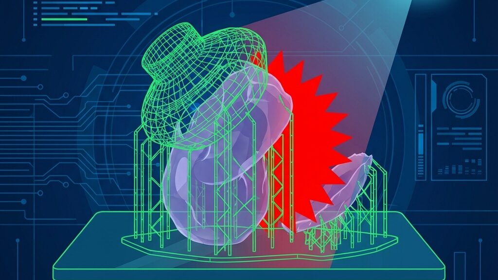
The third wall is invisible in CAD. An FDM print is not a uniform solid but a laminate of welded layers, and the weld is weaker than the filament itself. Polymaker publishes measured data in its technical data sheets: tensile strength around 31.1 MPa in the layer plane versus 16.7 MPa across layers for its popular PLA line — roughly half. Load applied in the direction that peels layers apart finds the weakest link every time.
The countermeasure costs nothing: orient the print so working loads run parallel to the layers, not across them. A hook printed flat on the bed survives; the same hook printed upright shears at a layer line. Before optimizing infill or walls, get the orientation right — it is the single largest strength lever available.
Beyond the three walls waits an ambusher: environment. PLA, the friendliest material to print, softens near its glass transition around 60 °C — a temperature the inside of a parked car exceeds on a summer afternoon. A phone mount that survived winter sags in July. PETG holds to roughly 75 °C and shrugs off humidity, which is why it is the default recommendation for indoor functional parts. Nylon is tougher still but drinks moisture from the air and must be dried before use. Matching material to environment is part of design, not an afterthought.
How do the AI design tools stack up once you care about function? Text-to-CAD produces parametric solids with real dimensions — the best starting point, but its numbers are guesses about your world and must be corrected by measurement. Generative design explores load-bearing shapes and respects the constraints you feed it, but it only knows the loads you declare. Code CAD through an LLM, such as OpenSCAD generation, is the most correctable: every dimension is a named variable you can patch in seconds after a test fit. Mesh generators aimed at figurines sit outside this discussion — their output lacks the dimensional intent functional parts require.
The common thread: every lineage produces a first draft. The revision loop — print, measure, correct — remains human work, and the tools that make revision cheap are the tools that win for functional parts.
If one purchase separates people who make usable parts from people who make shapes, it is a pair of digital calipers. A basic unit costs less than two spools of filament and converts every failed print from frustration into data. Measure the hole that was too tight and you know your machine prints holes 0.15 mm under nominal. Measure the boss that cracked and you know the wall was 1.2 mm where it needed 2.4. The printed part becomes a report about your printer, written in a language calipers translate.
Pair the calipers with a habit: measure the real-world object before modeling, measure the print after, and write both numbers down. Three or four cycles of this build a personal correction table more valuable than any online settings guide, because it describes your machine, your filament, your climate.
The Mitutoyo model discussed in this section, and a budget digital caliper that is enough to start the measuring habit.

 ポチップ
ポチップBefore slicing a functional part, answer seven questions. One: which dimensions are constrained by other objects, and have you measured those objects with calipers rather than trusted a spec sheet? Two: where does load enter the part, and does it run parallel to the layers? Three: which mating features need clearance, and how much? Four: what temperature and humidity will the part live in, and does the material survive that? Five: are there sharp inside corners that will concentrate stress? Six: if the fit is wrong by 0.2 mm, which variable in the model will you change? Seven: what is the cheapest test piece that answers the riskiest question before the six-hour print?
The seventh question is the professional habit in miniature. A 15-minute test coupon that validates a single critical fit saves evenings of full reprints, and it is exactly the discipline that AI-generated geometry — however elegant — will never perform on your behalf.
AI collapsed the cost of producing shapes, and in doing so revealed where the real work lives: in dimensions that must be measured, tolerances that must be designed, and layer directions that must be respected. None of the three walls falls to a better prompt. Each falls to a cheap tool, a small test, and a note in a logbook. This article opens a series that walks each wall in depth — tolerances and fit, threads and inserts, snap-fit design, strength engineering, repair practice, and a reverse-lookup roadmap that ties them together. Learn the walls once, and every AI tool in the stack becomes dramatically more useful, because you become the part of the loop that physics actually answers to.