Where the GPT-6 Astra Price Table Jumps Before You Fill a Million Tokens
swiftwand swiftwand.ai
Throw tools into a generic bin and they roll every time the drawer opens. Screwdrivers stack, pliers tangle. What you want is not a box but a cradle shaped to the tool. That means getting the outline of the tool into CAD, and measuring one with calipers to build a polygon is tolerable once and demoralising ten times over.
This article contains affiliate links. As an Amazon Associate, we earn from qualifying purchases.
The old approaches worked. Trace the tool onto paper with a pencil and scan the sheet as an underlay. Or set it on graph paper and read coordinates by eye. Both function, and both degrade as curves multiply. The thin nose of a pair of pliers comes out fatter than it is when traced by hand, and a recess built from that outline is loose everywhere. Tedium and sloppiness arrive together, which is what makes this step unpleasant.
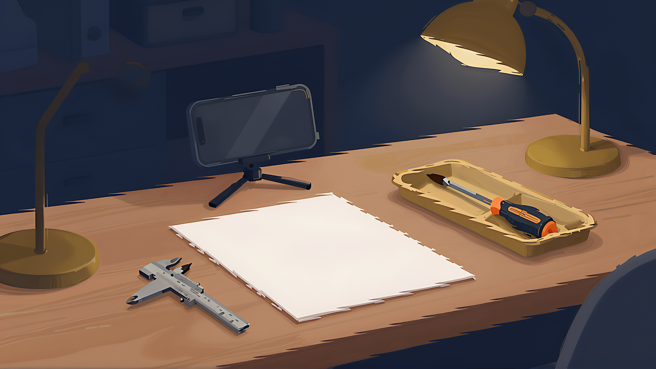
There is a tool that replaces that step with a single photograph. Lay the tools on paper, shoot from above, and software extracts the outlines and generates a bin with matching recesses. AI-assisted jig design becomes meaningful precisely in a bounded step like this one. You are not asking it to invent a shape. You are asking it to read an outline.
This article takes apart the mechanism and its limits, and sorts out where the machine stops and the human starts.
The conclusion first: in this workflow the AI does roughly thirty percent. Tracing is genuinely automated, but the clearance, the depth, and the finger access are all decided by a person. It is still worth having, because that thirty percent is the most tedious part and the part where humans get careless.
The published workflow runs in eight steps, for the MIT-licensed tool of this kind.
Step three is the interesting one. A photograph has no dimensions. The camera height and angle differ every time. Using a sheet of paper with known dimensions as the reference solves that, and the calibration stays visible so you can see whether it went wrong.
It also matters that the task is detection rather than recognition. The model does not need to identify what the object is, only to separate the object from the background. So an unusual tool, a part you made yourself, or something with no name in any dataset all behave the same. The weakness generative models have with objects outside their training data does not bite here.
Tools used in jigs have clear outlines, which is the regime this class of model handles well. Transparent acrylic items and black tools against a dark background are the hard cases, which is what makes the model choice matter.
With no API key configured, local models run. No network, no cost. Three are selectable by default.
| Model | CPU time | Minimum memory | Character |
|---|---|---|---|
| IS-Net (default) | about 0.8 s | 2 GB | Fastest, lowest memory |
| BiRefNet Lite | about 3.6 s | 8 GB | Handles reflections and shiny surfaces well |
| InSPyReNet | about 2.8 s | 6 GB | Apple Silicon (MPS) support |
A factor of four in memory is the practical dividing line. A separate model detects the four paper corners at the same time, and the memory figures above are documented as including both models.
Quality differences show up on shiny tools. Chrome-plated wrenches and stainless rules bounce the light and blur their own outline. The reflection-tolerant model costs more memory, and it earns that back if it saves you retakes. It is a straight trade between compute and effort.
The practical approach is to run everything through the light default first. Most tools have matte plastic or rubber grips and trace cleanly. Reshoot only the ones that do not, using the heavier model. There is no reason to process everything with the expensive one. If the machine in front of you has under 8 GB of main memory, the options narrow anyway, so check that first.
The typical reasons for a retake are worth listing. Tools touching each other get traced as one blob. A hard shadow on the paper puts the shadow edge into the outline. Low contrast between the grip and the paper, a pale grey tool on white, blurs the boundary. All of these are solved by arrangement and lighting, so fix how you shoot before you change the model. Leaving a finger width between tools handles most of it.
Deciding what runs locally versus in the cloud is exactly the trade-off foundation-model engineering covers.

 ポチップ
ポチップDistribution is container-based, so setup is not heavy. A few conditions apply.
The thing worth planning for at setup is storage. Extracted outlines are an asset you reuse, so without a volume outside the container you go back to photographing every time you rebuild. A tool outline, once captured, stays useful for years, and you will regroup the same tools into different layouts later. Decide where the library lives before you start.
Not needing a GPU is unusual in this field. This is not running a large generative model; it is separating foreground from background, which is small enough for a CPU. That also means an old laptop or a single-board computer can do the work, which changes where you can run it.
This is the core of it. What the photograph gives you is the projected exterior of the tool. Turning that into a usable cradle requires human judgement on top.
| Decision | Content |
|---|---|
| Clearance | An exact outline will not accept the tool. Add a gap you can insert and remove through |
| Depth | How much of the tool to bury. Too deep and you cannot get it out |
| Finger access | Where to cut the notch you pinch it by |
| Orientation | A layout that resists movement when the drawer opens and closes |
| Stepping | Stacked or laid flat |
Depth needs a note of its own. The photograph gives you a shape projected onto a plane and carries no thickness information. A pair of pliers is thicker at the joint than at the tip, and a recess of uniform depth either swallows the tip or leaves the joint proud. That is a human decision every time, and no amount of tracing accuracy substitutes for it.
Clearance is a fit problem, and fit problems have a general answer. The method for finding the gap your machine actually needs is in the article on tolerance and fit. Print a stepped test piece once and reuse the number.
Keeping the three inputs separate is the design principle here: the outline comes from the photograph, the dimensions come from the standard, and the judgement comes from you. Mixing them is what produces a cradle that fits nothing. The generator side of this is covered in the parametric generator comparison.
To be straightforward: this article is not a record of running these tools in our own environment. Everything here comes from published documentation, including the processing times and memory requirements, which are figures the distributor states. They will vary with the environment.
Why write it without running it. The value of this tool lies less in the feel of using it than in the design of the workflow around it. How to shoot, which model to choose, whether photographs leave your machine, where the human takes over. Those are decided before you run anything, and organising how to decide them has independent value.
Where a write-up is not backed by execution, we say so. That policy is consistent across this site, and exists to keep numeric backing and experiential backing from being confused with each other.
If you want to try it yourself, the path is short. Paper, tools, and the camera you already have gets you photographing today, and the tracing runs the same day you install it. The first thing to establish is whether your own tools separate cleanly. Shiny tools mean the heavier model; black plastic tools make it a question of contrast against the paper. One tool tells you what the other thirty will do.
Trying to build a cradle for every tool ends in running out of steam partway. There is a priority order.
Some things can wait. Anything you can throw in a box without consequence, meaning consumables that are uniform in shape and numerous, is fine in a generic divided bin. There is no point cutting an individual recess for each screw and washer.
This line gets drawn at photography time. Only the tools worth a cradle go on the paper. Narrowing what you shoot is the same act as estimating how much work you are taking on.
Do not do it all at once, either. Make five cradles and use them for two weeks. Too shallow, not enough finger access, better the other way round: none of that surfaces until you use it. The corrections from those two weeks make the next twenty better than the first five were.
A photograph replaces the worst step of jig design, and only that step. To recap:
Once you have the outlines, the bins themselves come from a parametric generator, and the drawer they go into needs measuring first. The series index is the workshop reverse guide.